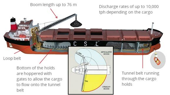
Gravity-fed self-unloaders with hoppered holds and gravity gates are the mainstay of on board a self -unloader. These vessels are suitable for granular free-flowing cargoes.
As the name implies, these vessels use gravity to release cargo through gates located at the bottom of the vessel's cargo holds onto conveyor belts running beneath the cargo area. The cargo is then transported to an elevating system, lifted above deck level and transferred onto a discharge boom conveyor. The cargo is offloaded via the discharge boom, port or starboard, depending on the unload facility.
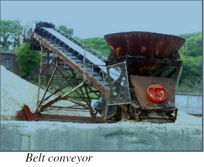
Loop belt, incline belt and bucket elevator self-unloading systems are all gravity-fed technologies. New belts are normally installed by Motors Technicians, however the following points are to be noted when handling a new belt: Stowage of a spare or new belt;
A stand is to be fabricated so that the roll of the belt is resting on a bar or pipe, passed through the centre of the roll.
Fig: Self unloader how it works
The stand is to be constructed so that the belt is clear of the deck.
The belt is to be wrapped in plastic or canvas to protect it from moisture and mechanical damage.
It must not be stowed in a place where hotwork is frequently carried out.
The hoisting bar is to be passed through the centre of the crate (belt); and a spreader used when hoisting.
The crate is to be rolled in the direction of the arrow marked on the face of the crate; rolling in the opposite direction will loosen or telescope the belt.
The belt is factory rolled with its carrying side out.
The hoisting bar acts as part of a de-reeling stand, on which the new belt is placed before threading onto the conveyor.
If the belt is required to be laid out keep the bends as large as possible; and ensure that it does not kink, and no undue strain is applied. No weights are to be placed on the laid out belt. Folds in the belt remain latent, only to manifest as fractures in the carcase during use.
Do not drag the belt. While feeding the belt onto the carriage, use the de-reeling arrangement, and make sure that it is not being pulled over any broken roller etc.
Clear and clean the area where the belt splicing is to be carried out After installation of a new belt, the running-in procedure is very important, and this can have a significant effect on the life of the belt. Therefore, the proper procedure has to be followed:
Check that all tools and equipment have been removed from the new belt and surrounding area before start-up.
Check that all pull cords have been reconnected and that pull cord switches have been reset.
Open the hydraulic valve to the tensioning cylinder and switch on the tensioning pump motor.
Check the splice area when tension is applied.
Check tensioning of carriage and associated wire ropes.
Check all personnel are clear of the belt and start it in the manual mode having a man stand by the switch box.
Observe the tracking of the belt and stop it immediately if the belt runs rapidly off track.
Carry out training adjustments as required to the rollers and/or pulleys.
Stop the belt and check the splice area again.
Re-install and tension the belt scrapers.
Run the belt again and check splice area.
Observe the belt closely during the first discharge of cargo, as the belt may track differently when loaded with cargo.
Belt checks, tracking and training
The term tracking applies to the running alignment of a conveyor belt. The term training applies to the adjustments carried out to track the belt correctly.
When a belt is tracking correctly it is running in the centre of its track and is therefore free from edge contact with steel work. A correctly trained belt will not make contact with the side guide rollers, except in the case of the Flexowell Lift Belts where the belt is always in contact with the rubber side guide wheels. A conveyor belt must not be operated if the edge of the belt is in contact with any steelwork, as this will cause serious damage to the belt.
When a new belt has been fitted it is often necessary to carry out some training adjustments. The pillow block bearings fitted to the spindles of all the large diameter pulleys in the belt system have slotted holes for their base bolts. There are also jacking screws fitted at each bearing base. This allows the lateral alignment of the pulleys to be adjusted. The brackets supporting the return rollers are also slotted for the same reason, as are the carriage frames.
Although every effort have been taken to improve the accuracy of content provided the publisher of this website cannot take responsibility for errors. DisclaimerPrivacy policyHome page