
Self unloading bulk carriers - How the system works?
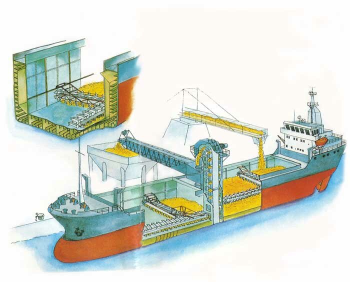
Self-unloaders are specialized ships equipped with onboard cargo-handling systems, enabling them to discharge without shore-based unloading equipment. The self-unloading system works in three broad stages:
The reciprocation of the ladder is in the fore and aft plane. The ladder is powered by two large hydraulic rams. The advantages of the N.C.Feeder are that there is a reduction in the amount of hydraulic machinery required as there are only two hydraulic rams per cargo hold and the system is easy to automate. The flow rate from an N.C.Feeder is controlled by the speed of reciprocation of the ladder. The action of the reciprocating motion keeps the cargo above in a constant state of flux. This allows the N.C.Feeder to handle cargoes of a very sticky nature, which might result in problems with other types of gates.
Hold conveyor belt
The Hold conveyor belt or tunnel belt runs under the cargo holds i.e. under the gates. Two or three are fitted depending on the width or design of the vessel.
The direction of travel of the belts carrying side is determined by the location of the transfer belts which transfer the cargo to the lift belt/s. All belts are spliced to form endless loops, around the drive pulley at one end, and a tail pulley at the other. An electric motor powers the drive pulley coupled through a Fluidrive coupling, and a reduction gear box. . The tunnel belts are tensioned using a hydraulically operated tensioning carriage, which can be situated at the forward or aft end of the belts (depending upon the ship design).
Transfer belts
Transfer belts are short athwartship running belts, which receive the cargo from the hold conveyor via the transfer hopper, and convey it to the lift belt via the centre hopper.
Usually there are two transfer belts from the two outer hold conveyors to the centre on either side. The transfer area is where the cargo changes direction, by being transferred from one belt to another via hoppers or bins. This is a high risk area as there is a concentration of drive elements. Protection to personnel provided by catwalks, guard rails, protective covers and signboards, and is essential. Water leaks into the tunnel accumulate in the transfer area if it is located aft. Care must be taken to ensure that the tunnel bilge levels do not rise, and must be attended to. The trash pump bilge wells are also located beneath the transfer area at the aft of the end vessels. These wells are fitted with water level alarms, which must be regularly tested to prove that they are operational.
Hoppers
The hoppers serve as transfer points for the transfer of cargo between two belt systems e.g. hold conveyor and transfer belt: between the transfer belt and the lift belt; and between the lift and boom belts.
The size and design of the boom or hopper depends upon the width and carrying capacity of the belts they serve, as they regulate and spread the cargo over the belt they feed. The belt carriage sides may also be fitted with skirtboards for further regulation of cargo. These bins or hoppers are lined witabrasion resistant liners to protect the mild steel construction, and hardened-impact plates on the side of direction of the cargo flow.
They may also be provided within their structure, with an adjustable plate to fine tune the cargo regulation, and avoid spillage. These bins or hoppers must be regularly inspected, for wear of their abrasive lining, and impact plates, and also that there are no other blockages e.g. previous cargo build-up, some fallen object, or any sharp object which would tend to tear the belt. During the discharging operation, inspections using a torch through the viewing-ports provided, are to be carried out.
Related information